The Perfect Part Exists Only in CAD: Bridging Design Intent and Machinable Reality
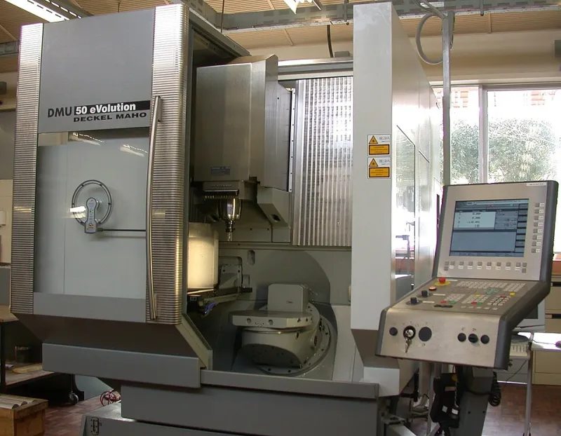
Photo: Unknown, CC BY-SA 2.0, via Wikimedia Commons
A CAD model is a beautiful lie. Not intentionally — the geometry is exact, the datums are clean, and every hole sits precisely where it was placed. But a solid model carries no memory of the machine that will cut it. It knows nothing about the 0.0002-inch runout at the end of a long tool, the half-degree of thermal growth a spindle picks up over a four-hour cycle, or the way a thin-walled part moves the moment a fixture clamps it.
The gap between design intent and machined reality is where most cost overruns are born. Understanding that gap — and designing around it — is one of the cheapest forms of engineering available.
Runout: The Error Nobody Quotes
Spindle runout is the small rotational error between where the tool is supposed to be and where it actually is. A healthy machining center might hold total indicated runout under 0.0002 inches at the spindle nose. But that error compounds: add toolholder concentricity, a long slender end mill, and cutting forces, and the effective error at the cutting edge can triple or quadruple.
For a drilled hole with a ±0.005-inch tolerance, this is irrelevant. For a reamed dowel hole specified at +0.0002/-0.0000 inches, runout is the difference between a part that passes CMM inspection and a cart headed for the scrap bin.
The practical takeaway for designers: the tighter the bore tolerance, the more the process — not the print — dictates the outcome. If your drawing demands precision beyond what a single standard tool can hold, the shop has to budget for dedicated tooling, boring heads, or finish machining on a second operation. All of that shows up on the quote.
Thermal Drift: The Error That Moves
A spindle that runs cold at 7:00 AM is not the same spindle at 11:30 AM. Bearings warm up, ball screws lengthen, and the machine's column grows by fractions of a thousandth. On a 20-inch part, a 0.0003-inch thermal shift in the Z-axis is invisible on a bracket and catastrophic on a sealing surface.
Shops manage this with warm-up cycles, probing, and compensation — but those strategies cost time. A drawing that scatters critical dimensions across faces machined hours apart forces the shop to re-establish references repeatedly. Consolidating critical features so they can be cut in one setup, on one warmed machine, is a design decision that quietly saves money.
Fixture Deflection: The Error You Create
Here is the uncomfortable one: some of the error in a finished part comes from the workholding, and the workholding behaves the way the part dictates. Clamp a thin-walled aluminum housing at four points with reasonable torque and the walls bow inward. The cutter machines a perfectly flat surface onto a deflected part. Release the clamps, and the surface is no longer flat.
Experienced machinists compensate with softer jaws, vacuum fixtures, or strategic clamping — but the designer controls the raw material. Adding a rib where clamping force lands, specifying a datum scheme that survives realistic clamping, and tolerancing walls with an eye toward rigidity all reduce the problem before the part ever touches a vise.
A Pre-RFQ Checklist for Design and Procurement Teams
Before releasing a drawing for quote, run it through these six questions:
- Are any tolerances tighter than the function requires? A ±0.0005-inch callout copied from a legacy drawing deserves re-justification, not repetition.
- Do critical bores specify a tolerance that requires single-pass precision? If yes, expect dedicated tooling costs.
- Can all critical features be machined in one setup? Multi-setup criticals multiply cumulative error.
- Is the part rigid enough for conventional workholding? Thin sections and long overhangs should be flagged and discussed.
- Are datums physically accessible and stable under clamping? A datum face that deflects is not a datum.
- Has anyone asked a machinist? Fifteen minutes with a manufacturing engineer before release routinely saves weeks after it.
The Spec Is a Conversation
The best drawings we see are not the ones with the fewest notes — they are the ones that show the designer understood the part would be cut from solid metal by a machine that drifts, deflects, and wears. Treat the print as the opening of a conversation with your supplier, not a final verdict. The parts that ship on time, at tolerance, and at the quoted price almost always come from drawings that were written with the machine tool in mind.